RC, LR and LC Circuits: Growth, Decay and Oscillation
What to remember
- A capacitor will not let its voltage change in an instant, and an inductor will not let its current change in an instant. Every transient problem starts from this one rule.
- RC charging: $q = Q(1 - e^{-t/RC})$ and $i = \frac{\varepsilon}{R}e^{-t/RC}$. LR growth: $i = I_0(1 - e^{-Rt/L})$. The time constants are $\tau = RC$ and $\tau = L/R$. After one $\tau$ a growing quantity has covered 63% of its way to the final value, and a decaying one has fallen to 37%.
- Charging a capacitor through any resistor from a battery: the battery gives $C\varepsilon^2$, the capacitor keeps $\frac{1}{2}C\varepsilon^2$, and the resistor turns the other $\frac{1}{2}C\varepsilon^2$ into heat. The value of $R$ changes how long this takes, never how much heat appears.
- A capacitor and an inductor with no resistance exchange energy for ever: $q = Q\cos\omega t$ with $\omega = \frac{1}{\sqrt{LC}}$. Add a resistor in series with an ac source and you get resonance at the same $\omega_0$, with sharpness measured by $Q = \frac{\omega_0 L}{R}$.
- At $t = 0$ an uncharged capacitor acts like a plain wire and an inductor with no current acts like a cut wire. At $t \to \infty$ in a dc circuit the roles swap: the capacitor is a cut wire and the inductor is a plain wire.
Self-inductance, and what C and L do at the two extremes
A coil carrying current $i$ has flux through itself, $\Phi = Li$, where $L$ is its self-inductance (unit henry, H). When the current changes, the coil produces an emf that opposes the change:
The energy stored in the magnetic field when the current is $I$ is
You can see where it comes from. To raise the current by $di$ against the opposing emf, the source must do work $L\,i\,di$, and adding these up from $0$ to $I$ gives $\frac{1}{2}LI^2$. A capacitor is the electric twin of this: $q = CV$, energy $\frac{1}{2}CV^2 = \frac{q^2}{2C}$, and the current into it is $i = \frac{dq}{dt}$.
Now the two memory rules that decide almost every question in this chapter.
- Voltage across a capacitor, $V = q/C$, is continuous. For it to jump, $q$ would have to jump, which needs infinite current.
- Current through an inductor is continuous. For it to jump, $di/dt$ would be infinite, which needs infinite emf.
Everything else (the current through a capacitor, the voltage across an inductor, the currents in other branches) is free to jump at the instant a switch is closed.
| Element | At $t = 0^+$ (state at switching) | At $t \to \infty$ (dc steady state) |
|---|---|---|
| Capacitor, initially uncharged | Acts like a wire, $V = 0$ | Acts like a gap, $i = 0$, $V = \varepsilon_{\text{across it}}$ |
| Capacitor with charge $q_0$ | Acts like a battery of $q_0/C$ | Acts like a gap, $i = 0$ |
| Inductor, initially no current | Acts like a gap, $i = 0$ | Acts like a wire, $V = 0$ |
| Inductor with current $I_0$ | Acts like a current source of $I_0$ | Acts like a wire, $V = 0$ |
Memory trick: "C is Closed at the start, Open at the end. L is the opposite: Open at the start, Closed at the end!"
Say it before you redraw any circuit for $t = 0^+$ or $t = \infty$. Then solve it as a plain resistor network.
Example 1: A battery of 12 V, a resistor $R_1 = 4\ \Omega$, and a parallel pair made of $R_2 = 6\ \Omega$ and an ideal inductor $L$, all in series. The switch is closed at $t = 0$. Find the battery current just after closing and a long time later.
Just after closing: the inductor has no current, so it is a gap. The parallel pair is only $R_2$.
$I(0^+) = \frac{12}{4 + 6} = 1.2$ A.
A long time later: the inductor is a wire and it shorts out $R_2$.
$I(\infty) = \frac{12}{4} = 3$ A.
The current through the inductor itself climbs from 0 to 3 A, while the current through $R_2$ falls from 1.2 A to 0.
Why this works: only the inductor current is forced to be continuous. The battery current is not, and it jumped from 0 to 1.2 A at once.
RC circuit with a dc source: charging
A battery $\varepsilon$, resistor $R$ and uncharged capacitor $C$ are in series. Close the switch at $t = 0$. At any instant the loop rule gives
So $\frac{dq}{dt} = \frac{C\varepsilon - q}{RC}$. Put $Q = C\varepsilon$ (the final charge) and separate the variables:
Differentiating gives the current, and dividing by $C$ gives the capacitor voltage:
The quantity $\tau = RC$ has the unit of time (ohm times farad is second). It is the time in which the current would drop to zero if it kept falling at its starting rate, and it is also the time in which $q$ reaches $(1 - 1/e) = 0.632$ of $Q$.
| $t$ | $q/Q$ (charging) | $i/i_0$ |
|---|---|---|
| $0$ | $0$ | $1$ |
| $\tau$ | $0.632$ | $0.368$ |
| $2\tau$ | $0.865$ | $0.135$ |
| $3\tau$ | $0.950$ | $0.050$ |
| $5\tau$ | $0.993$ | $0.007$ |
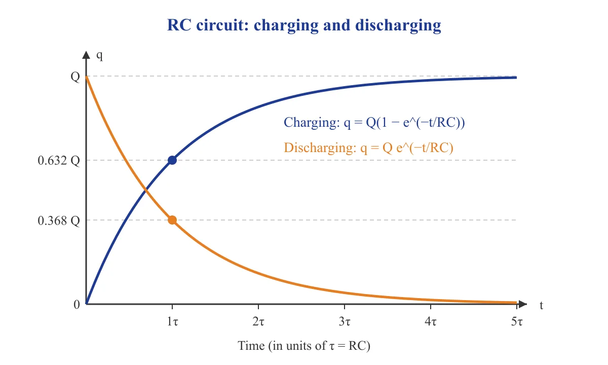
Figure 3.1: Charging and discharging of a capacitor through a resistor. The same shape describes current in an LR circuit.
Notice two things about the graph. The slope at $t = 0$ is the steepest, because the current is largest then. And the curve never truly reaches $Q$; after $5\tau$ it is within 1% of it, which is the practical meaning of "fully charged".
Example 2: A $5\ \mu$F capacitor is charged through a $2\ \text{M}\Omega$ resistor from a battery. How long does it take to reach 90% of its final charge? ($\ln 10 = 2.303$)
$\tau = RC = 2\times10^6 \times 5\times10^{-6} = 10$ s.
$0.9 = 1 - e^{-t/\tau}$, so $e^{-t/\tau} = 0.1$.
$t = \tau\ln 10 = 10 \times 2.303 = 23$ s.
Why this works: to ask for a given fraction of the way, set $e^{-t/\tau}$ equal to the fraction still to go, then take a log.
Discharging, energy and heat
Remove the battery and join the charged capacitor ($q_0$) to the resistor. Now $iR + \frac{q}{C} = 0$ with $i = -\frac{dq}{dt}$ (the charge is falling), so
The capacitor voltage and the current both decay with the same $\tau = RC$. The orange curve in Figure 3.1 shows it.
Energy bookkeeping while charging. The battery pushes a total charge $Q = C\varepsilon$ through a potential rise of $\varepsilon$, so it supplies
The capacitor finally holds $\frac{1}{2}C\varepsilon^2$. The rest is heat in the resistor. You can check it by integration:
Heat equals stored energy, for any $R$. A big $R$ makes the current small but makes it last long, and the two effects cancel.
Energy bookkeeping while discharging. The stored $\frac{1}{2}CV_0^2$ all becomes heat in $R$, again whatever the value of $R$.
Example 3: A $40\ \mu$F capacitor charged to 100 V is discharged through a $50\ \Omega$ resistor. Find the heat produced, and the time at which the stored energy has fallen to one-fourth.
Heat $= \frac{1}{2}CV^2 = \frac{1}{2}\times 40\times10^{-6}\times 10^4 = 0.2$ J. The $50\ \Omega$ is not needed for this.
Energy $\propto q^2$. One-fourth energy means $q = q_0/2$.
$e^{-t/\tau} = \frac{1}{2}$, so $t = \tau\ln 2$, with $\tau = 50 \times 40\times10^{-6} = 2$ ms.
$t = 2 \times 0.693 = 1.39$ ms.
Why this works: energy goes as the square of charge, so "energy $\frac{1}{4}$" means "charge $\frac{1}{2}$", not "$e^{-t/\tau} = \frac{1}{4}$".
Memory trick: "Half in the cap, half in the heat, whatever the R!"
When asked for heat in charging from a battery, write $\frac{1}{2}C\varepsilon^2$ at once and ignore $R$.
LR circuit: growth and decay of current
A battery $\varepsilon$, a resistor $R$ and an inductor $L$ in series. Close the switch at $t = 0$. The loop rule is
This has the same shape as the capacitor equation, with $i$ playing the role of $q$. Let $I_0 = \varepsilon/R$ be the final current. Then $L\frac{di}{dt} = R(I_0 - i)$ and
The time constant is $\tau = L/R$. A large $L$ means a sluggish circuit; a large $R$ means a fast one that settles at a smaller current $\varepsilon/R$.
At $t = 0$ the current is zero, so the whole emf appears across the inductor, and the initial rate is $\left.\frac{di}{dt}\right|_0 = \frac{\varepsilon}{L}$. This rate does not depend on $R$.
Decay. If the battery is removed and the coil, carrying $I_0$, is closed through the resistor, then $iR + L\frac{di}{dt} = 0$:
The magnetic energy $\frac{1}{2}LI_0^2$ turns completely to heat in $R$. If you open a switch carelessly in series with a big inductor, $di/dt$ becomes very large, the induced emf can be thousands of volts, and you get a spark across the switch. That is why such circuits have a path for the current to decay.
| Feature | RC charging | LR growth |
|---|---|---|
| Quantity that cannot jump | $V_C$ (charge) | $i$ (current) |
| Time constant | $RC$ | $L/R$ |
| Rising quantity | $q = Q(1 - e^{-t/\tau})$ | $i = I_0(1 - e^{-t/\tau})$ |
| Falling quantity | $i = \frac{\varepsilon}{R}e^{-t/\tau}$ | $V_L = \varepsilon e^{-t/\tau}$ |
| Final energy stored | $\frac{1}{2}C\varepsilon^2$ | $\frac{1}{2}L\left(\frac{\varepsilon}{R}\right)^2$ |
| Battery work / heat | work $= C\varepsilon^2$, heat $= \frac{1}{2}C\varepsilon^2$ | heat grows without limit while current flows |
Example 4: A coil of $L = 0.5$ H and $R = 10\ \Omega$ is connected to a 20 V battery of negligible resistance. Find (a) the initial $di/dt$, (b) the time when the current is 1 A, (c) the energy stored at the end. ($\ln 2 = 0.693$)
(a) $\frac{di}{dt} = \frac{\varepsilon}{L} = \frac{20}{0.5} = 40$ A s$^{-1}$.
(b) $I_0 = \frac{20}{10} = 2$ A and $\tau = \frac{0.5}{10} = 0.05$ s. Half of the final current: $1 - e^{-t/\tau} = \frac{1}{2}$, so $t = \tau\ln 2 = 0.05\times0.693 = 0.035$ s.
(c) $U = \frac{1}{2}LI_0^2 = \frac{1}{2}\times0.5\times4 = 1$ J.
Why this works: part (b) is the "half-way" time, which is $0.693\,\tau$ for every exponential rise. Remember it.
The power in the inductor. While the current grows, the battery delivers $\varepsilon i$, the resistor takes $i^2R$ and the inductor stores energy at the rate $P_L = L\,i\,\frac{di}{dt}$. Put $x = t/\tau$: $P_L = \frac{\varepsilon^2}{R}(1 - e^{-x})e^{-x}$. This is zero at $t = 0$ (no current) and at $t \to \infty$ (no $di/dt$), and it is largest when $e^{-x} = \frac{1}{2}$, that is at $t = \tau\ln 2$. At that moment the current is half of its final value.
LC oscillations
Charge a capacitor to $Q$, then connect it across an inductor with no resistance. The loop rule gives $\frac{q}{C} + L\frac{di}{dt} = 0$, and with $i = \frac{dq}{dt}$:
This is the equation of simple harmonic motion with $\omega^2 = \frac{1}{LC}$. Compare it with a spring: $\frac{d^2x}{dt^2} = -\frac{k}{m}x$. The dictionary is $q \leftrightarrow x$, $i \leftrightarrow v$, $L \leftrightarrow m$ (inductance resists change of current as mass resists change of velocity), and $\frac{1}{C} \leftrightarrow k$. Hence
Starting with full charge at $t = 0$:
The current's magnitude peaks at $I_m = Q\omega$ when $q = 0$.
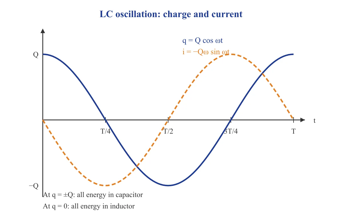
Figure 3.2: Charge and current in an LC circuit. They are a quarter-period apart, so one is at its extreme when the other is zero.
Energy exchange. At any time
The sum is $\frac{Q^2}{2C}$, constant. Here $\frac{1}{2}LI_m^2 = \frac{1}{2}LQ^2\omega^2 = \frac{Q^2}{2C}$, which agrees. The capacitor energy and inductor energy each oscillate at twice the frequency of $q$, because $\cos^2$ and $\sin^2$ repeat every half period.
| Time | Charge on C | Current | Energy location |
|---|---|---|---|
| $0$ | $+Q$ | $0$ | all in capacitor |
| $T/8$ | $Q/\sqrt{2}$ | $I_m/\sqrt{2}$ | shared equally |
| $T/4$ | $0$ | $I_m$ (magnitude) | all in inductor |
| $T/2$ | $-Q$ | $0$ | all in capacitor, reversed |
| $3T/4$ | $0$ | $I_m$ (opposite direction) | all in inductor |
Example 5: An inductor of $L = 0.1$ H and a $10\ \mu$F capacitor charged to $Q = 200\ \mu$C form an LC circuit. Find $\omega$, the peak current, and the current when $q = Q/2$.
$\omega = \frac{1}{\sqrt{LC}} = \frac{1}{\sqrt{0.1\times10\times10^{-6}}} = \frac{1}{10^{-3}} = 1000$ rad s$^{-1}$.
$I_m = Q\omega = 200\times10^{-6}\times1000 = 0.2$ A.
At $q = Q/2$: use energy. $U_C = \frac{1}{4}$ of the total, so $U_L = \frac{3}{4}$ of the total, which means $i^2 = \frac{3}{4}I_m^2$.
$i = 0.2\times\frac{\sqrt3}{2} = 0.173$ A.
Why this works: when $q$ is a fraction $f$ of $Q$, the capacitor holds $f^2$ of the energy, so $i = I_m\sqrt{1 - f^2}$. Take care: use the energy, not a linear guess.
Example 6: The same circuit starts at $q = Q$ at $t = 0$. At what time does $q$ first become zero, and when is the energy first shared equally?
$q = Q\cos\omega t = 0$ at $\omega t = \frac{\pi}{2}$, so $t = \frac{\pi}{2\omega} = \frac{T}{4}$. With $\omega = 1000$, $t = 1.57$ ms.
Equal sharing needs $q = \frac{Q}{\sqrt2}$, so $\cos\omega t = \frac{1}{\sqrt2}$ and $\omega t = \frac{\pi}{4}$, giving $t = \frac{T}{8} = 0.785$ ms.
Why this works: an LC circuit is SHM, so the same quarter-period and eighth-period logic you use for a spring applies.
Memory trick: "Charge at the edge, current in the middle." In LC, when the capacitor is full the current is zero, and when the capacitor is empty the current is at its largest.
Use it to decide which of $q$, $i$, $U_C$, $U_L$ is zero at a given instant.
If a resistor is present in series with the oscillating pair, the oscillations die out. The amplitude then falls roughly as $e^{-Rt/2L}$ when $R$ is small. This is the electrical version of damping.
Series LCR with an ac source: resonance and quality factor
Connect $R$, $L$ and $C$ in series to a source $\varepsilon = \varepsilon_0\sin\omega t$. This is a forced oscillation: the source is the driver, the LC pair has its own natural frequency $\omega_0 = \frac{1}{\sqrt{LC}}$, and $R$ is the damping. Revision of the basic results:
- Reactances: $X_L = \omega L$, $X_C = \frac{1}{\omega C}$.
- Impedance: $Z = \sqrt{R^2 + (X_L - X_C)^2}$.
- Peak current: $I_0 = \frac{\varepsilon_0}{Z}$. Phase angle: $\tan\phi = \frac{X_L - X_C}{R}$. The current lags the emf when $X_L > X_C$ and leads it when $X_C > X_L$.
Resonance occurs when $X_L = X_C$, that is at $\omega = \omega_0 = \frac{1}{\sqrt{LC}}$. Then:
- $Z = R$ is minimum, so the current is maximum, $I_0 = \frac{\varepsilon_0}{R}$.
- The phase angle is zero and the power factor is 1.
- $V_L$ and $V_C$ are equal in size and exactly opposite in phase, so they cancel in the loop, even though each may be far larger than the source emf.
The mechanical analogy is a child on a swing pushed at the swing's own frequency: the push goes in the same direction as the velocity all the time. At resonance the source emf is in step with the current, and the energy it supplies each cycle only replaces what $R$ burns.
Quality factor. Define
At resonance $V_L = V_C = I_0X_L = Q\,\varepsilon_0$, so $Q$ is the voltage magnification. The width of the resonance curve (the range of $\omega$ where the power is at least half the maximum) is
Small $R$ gives large $Q$ and a tall, narrow peak. Radio tuning uses this: a high-$Q$ circuit picks one station and rejects its neighbours.
| Quantity | Below $\omega_0$ | At $\omega_0$ | Above $\omega_0$ |
|---|---|---|---|
| Which reactance is larger | $X_C$ | equal | $X_L$ |
| Circuit behaves like | $RC$ | pure $R$ | $RL$ |
| Current vs emf | leads | in phase | lags |
| Current amplitude | rising | maximum | falling |
Example 7: An LCR series circuit has $R = 10\ \Omega$, $L = 0.1$ H and $C = 10\ \mu$F, driven by a source of 20 V amplitude. Find $\omega_0$, $Q$, the bandwidth, the peak current at resonance, and the peak voltage across $C$ at resonance.
$\omega_0 = \frac{1}{\sqrt{0.1\times10^{-5}}} = \frac{1}{10^{-3}} = 1000$ rad s$^{-1}$.
$Q = \frac{\omega_0L}{R} = \frac{1000\times0.1}{10} = 10$.
$\Delta\omega = \frac{R}{L} = \frac{10}{0.1} = 100$ rad s$^{-1}$. Check: $\frac{\omega_0}{\Delta\omega} = 10$, matches $Q$.
$I_0 = \frac{20}{10} = 2$ A.
$X_C = \frac{1}{\omega_0C} = \frac{1}{1000\times10^{-5}} = 100\ \Omega$, so $V_C = 2\times100 = 200$ V $= Q\varepsilon_0$.
Why this works: the capacitor voltage is ten times the source voltage. The energy is not created. It is the stored energy shuttling between $L$ and $C$ while $R$ is topped up by the source.
Common traps
- Saying the capacitor current is zero at $t = 0$ in a charging circuit → current is $\varepsilon/R$ at $t = 0$, the maximum, because the capacitor is momentarily a wire.
- Treating the inductor like a wire at $t = 0^+$ → at $t = 0^+$ it carries its old current (zero if it had none), so it behaves like a gap or a current source.
- Writing $\tau = RC$ for an LR circuit, or $\tau = LR$ → LR has $\tau = L/R$; check that the unit is seconds.
- Using the time to reach 63% as "the time to charge fully" → full charge is only approached; $5\tau$ is a practical limit.
- Thinking the heat in charging depends on $R$ → it is always $\frac{1}{2}C\varepsilon^2$ for a battery charge of an initially uncharged capacitor.
- Solving "energy falls to one-fourth" as $e^{-t/\tau} = \frac{1}{4}$ → energy goes as $q^2$ (or $i^2$), so the amplitude factor is $e^{-t/\tau} = \frac{1}{2}$.
- Using $\tau = L/R$ with the wrong $R$ in a multi-resistor circuit → $R$ is the equivalent resistance seen by the inductor with the battery replaced by its internal resistance.
- Using $\omega = \frac{1}{LC}$ → there is a square root: $\omega = \frac{1}{\sqrt{LC}}$.
- Taking the capacitor and inductor energies in an LC circuit to oscillate at $\omega$ → each oscillates at $2\omega$, and their sum stays constant.
- Expecting $V_L$ and $V_C$ to cancel in magnitude only at resonance, and so concluding both are zero → they are each $Q\varepsilon_0$, equal and opposite in phase, and their phasor sum is zero.
Quick revision
- $\mathcal{E}_L = -L\frac{di}{dt}$, $U_L = \frac{1}{2}LI^2$; $U_C = \frac{1}{2}CV^2$.
- Capacitor voltage and inductor current are continuous; other quantities can jump.
- Uncharged $C$ at $t = 0$: a wire. $C$ at $t \to \infty$: a gap. $L$ at $t = 0$ with no current: a gap. $L$ at $t \to \infty$: a wire.
- RC charging: $q = Q(1 - e^{-t/RC})$, $i = \frac{\varepsilon}{R}e^{-t/RC}$, $Q = C\varepsilon$.
- RC discharging: $q = q_0e^{-t/RC}$, same $\tau = RC$.
- LR growth: $i = \frac{\varepsilon}{R}(1 - e^{-Rt/L})$, $\tau = \frac{L}{R}$, initial rate $\frac{\varepsilon}{L}$.
- LR decay: $i = I_0e^{-Rt/L}$.
- One time constant: growth reaches 63.2%, decay falls to 36.8%; two time constants: 86.5% and 13.5%.
- Time for half of the change: $0.693\,\tau$.
- Charging from a battery: work $C\varepsilon^2$, stored $\frac{1}{2}C\varepsilon^2$, heat $\frac{1}{2}C\varepsilon^2$, independent of $R$.
- Discharge or decay: all stored energy becomes heat in $R$.
- LC circuit: $\omega = \frac{1}{\sqrt{LC}}$, $q = Q\cos\omega t$, $I_m = Q\omega$, total energy $\frac{Q^2}{2C}$.
- At $q = fQ$ the current is $I_m\sqrt{1 - f^2}$.
- Series LCR resonance: $\omega_0 = \frac{1}{\sqrt{LC}}$, $Z = R$, phase $0$, $I_0 = \frac{\varepsilon_0}{R}$.
- Quality factor $Q = \frac{\omega_0L}{R} = \frac{1}{R}\sqrt{\frac{L}{C}} = \frac{\omega_0}{\Delta\omega}$ with $\Delta\omega = \frac{R}{L}$; $V_L = V_C = Q\varepsilon_0$ at resonance.
Practice questions
In a series RC circuit, the time constant is
- $RC$
- $1/(RC)$
- $R/C$
- $C/R$
Answer
A. $RC$
The time constant of an RC circuit is the product RC, with unit ohm times farad = second.
A resistor $R$ and an uncharged capacitor $C$ are connected in series to a battery of emf $\varepsilon$ and negligible internal resistance. The current immediately after the switch is closed is
- zero
- $\varepsilon/R$
- infinite
- $\varepsilon/(RC)$
Answer
B. $\varepsilon/R$
The uncharged capacitor has V = 0, so it acts as a wire and the whole emf falls across R: i = ε/R.
A long time after a switch is closed in a dc circuit containing an ideal inductor, the inductor behaves as
- an open gap carrying no current
- a battery of emf equal to the supply
- a resistor of value $L/R$
- a plain wire with zero potential difference across it
Answer
D. a plain wire with zero potential difference across it
In steady dc, di/dt = 0, so the induced emf L di/dt is zero; the ideal inductor is a short.
A coil of inductance $L$ and resistance $R$ is connected to a battery of emf $\varepsilon$. At time $t = L/R$ after closing the switch, the potential difference across the inductor is
- $0.5\,\varepsilon$
- $\varepsilon$
- $0.368\,\varepsilon$
- $0.632\,\varepsilon$
Answer
C. $0.368\,\varepsilon$
V_L = ε e^(−t/τ). At t = τ this is ε/e = 0.368 ε.
The frequency of an LC oscillator is $f$. If both $L$ and $C$ are made four times larger, the new frequency is
- $f/4$
- $f/16$
- $f/2$
- $4f$
Answer
A. $f/4$
f ∝ 1/√(LC). LC becomes 16 times, so f becomes f/√16 = f/4.
In an ideal LC circuit the maximum charge on the capacitor is $Q_0$. The charge on the capacitor at the instant when the energy is equally shared between the capacitor and the inductor is
- $Q_0/\sqrt{3}$
- $Q_0/4$
- $Q_0/\sqrt{2}$
- $Q_0/2$
Answer
C. $Q_0/\sqrt{2}$
Equal sharing: q²/2C = ½ of Q0²/2C, so q² = Q0²/2 and q = Q0/√2.
A capacitor $C$ charged to potential difference $V$ is discharged through a resistor $R$. The total heat produced in the resistor is
- $CV^2$
- $\tfrac{1}{2}CV^2$
- $\tfrac{1}{4}CV^2$
- $\tfrac{1}{2}CV^2(1 - 1/e)$
Answer
B. $\tfrac{1}{2}CV^2$
All the stored energy ½CV² ends up as heat, whatever the value of R.
An uncharged capacitor $C$ is charged through a resistor $R$ by a battery of emf $\varepsilon$ until the current stops. The work done by the battery is
- a value that depends on $R$
- $\tfrac{1}{2}C\varepsilon^2$
- $2C\varepsilon^2$
- $C\varepsilon^2$
Answer
D. $C\varepsilon^2$
Charge Q = Cε moves through a rise of ε: W = Qε = Cε². Half is stored, half is heat, independent of R.
A series LCR circuit has quality factor $Q$ at resonance. The resistance is halved and the inductance is doubled, with $C$ unchanged. The new quality factor is
- $4Q$
- $\sqrt{2}\,Q$
- $2\sqrt{2}\,Q$
- $2Q$
Answer
C. $2\sqrt{2}\,Q$
Q = (1/R)√(L/C). Halving R gives ×2, doubling L gives ×√2, so the product is 2√2.
A series LCR circuit, with a high quality factor $Q$, is driven at resonance by a source of amplitude $\varepsilon_0$. The peak voltage across the inductor is
- $\varepsilon_0$
- $Q\,\varepsilon_0$
- $\varepsilon_0/Q$
- zero
Answer
B. $Q\,\varepsilon_0$
At resonance I0 = ε0/R, V_L = I0 ω0 L = (ω0 L/R) ε0 = Q ε0. The net voltage across L and C together is zero, not V_L itself.
The SI unit of the ratio $L/R$, where $L$ is inductance and $R$ is resistance, is
- henry
- hertz
- ohm
- second
Answer
D. second
L/R is the time constant of an LR circuit, so its unit is the second.
In the charging of a capacitor through a resistor $R$, the time taken for the current to fall to half of its initial value is
- $RC\ln 2$
- $RC/2$
- $2RC$
- $RC$
Answer
A. $RC\ln 2$
i = i0 e^(−t/RC) = i0/2 gives t = RC ln 2.
A battery of emf $\varepsilon$ is connected across a resistor $R$ and an ideal inductor $L$ in series. The rate at which energy is stored in the inductor is greatest at time
- $\tfrac{L}{R}$
- $\tfrac{2L}{R}$
- $\tfrac{L}{R}\ln 2$
- $\tfrac{L}{2R}$
Answer
C. $\tfrac{L}{R}\ln 2$
P = L i di/dt ∝ (1 − e^(−x)) e^(−x), x = t/τ. Differentiate: e^(−x) = ½, so t = τ ln 2.
In an ideal LC circuit the peak current is $I_m$. At the instant the current is $I_m/2$, the fraction of the total energy stored in the capacitor is
- $3/4$
- $1/2$
- $1/\sqrt{2}$
- $1/4$
Answer
A. $3/4$
Inductor energy ∝ i², so it is ¼ of the total. The capacitor holds the remaining ¾.
A $2\ \mu$F capacitor is charged through a $1\ \text{M}\Omega$ resistor. The time constant, in seconds, is
- 0.5
- 4
- 8
- 2
Answer
D. 2
τ = RC = 10⁶ × 2×10⁻⁶ = 2 s.
A coil has inductance $300$ mH and resistance $15\ \Omega$. Its time constant in milliseconds is
- 0.02
- 20
- 45
- 200
Answer
B. 20
τ = L/R = 0.3/15 = 0.02 s = 20 ms.
A capacitor is charged through a resistor $R$ by a $20$ V battery of negligible internal resistance. At the instant when the current has fallen to one-fourth of its initial value, the potential difference across the capacitor, in volts, is
- 10
- 5
- 15
- 20
Answer
C. 15
V_C = ε − iR = ε(1 − i/i0) = 20 × ¾ = 15 V. Check: V_R = 5 V, and 5 + 15 = 20 V.
A $40\ \mu$F capacitor charged to $100$ V is discharged through a resistor. The heat produced, in joules, is
- 0.4
- 0.2
- 0.02
- 2
Answer
B. 0.2
H = ½CV² = ½ × 40×10⁻⁶ × 10⁴ = 0.2 J.
A coil of inductance $2$ H and resistance $6\ \Omega$ is connected to a $24$ V battery. When the current is $2$ A, the rate of change of current, in A s$^{-1}$, is
- 12
- 8
- 2
- 6
Answer
D. 6
ε = iR + L di/dt → 24 = 12 + 2 di/dt → di/dt = 6 A/s.
A coil of inductance $0.4$ H and resistance $5\ \Omega$ is connected to a $10$ V battery of negligible internal resistance. After a long time the energy stored in the coil, in joules, is
- 0.8
- 1.6
- 0.4
- 4
Answer
A. 0.8
I = 10/5 = 2 A. U = ½ L I² = ½ × 0.4 × 4 = 0.8 J.
An inductor of $0.25$ H and a capacitor of $1\ \mu$F form an ideal LC circuit. The angular frequency, in rad s$^{-1}$, is
- 1000
- 4000
- 2000
- 4000000
Answer
C. 2000
ω = 1/√(LC) = 1/√(0.25 × 10⁻⁶) = 1/(5×10⁻⁴) = 2000 rad/s.
A $1\ \mu$F capacitor charged to $100$ V is connected across an ideal $0.25$ H inductor. The peak current, in amperes, is
- 0.02
- 0.2
- 0.4
- 0.1
Answer
B. 0.2
Energy: ½CV² = ½LI² → I² = 10⁻⁶ × 10⁴ / 0.25 = 0.04, I = 0.2 A. Check: Q ω = 10⁻⁴ × 2000 = 0.2 A.
A series LCR circuit has $R = 5\ \Omega$, $L = 0.1$ H and $C = 40\ \mu$F. Its quality factor is
- 2
- 50
- 100
- 10
Answer
D. 10
ω0 = 1/√(0.1 × 40×10⁻⁶) = 500 rad/s. Q = ω0 L/R = 500 × 0.1/5 = 10. Check: (1/R)√(L/C) = 0.2 × 50 = 10.
A series LCR circuit has $R = 20\ \Omega$ and $L = 0.4$ H. The width of its resonance curve $\Delta\omega$, in rad s$^{-1}$, is
- 50
- 0.02
- 20
- 8
Answer
A. 50
Δω = R/L = 20/0.4 = 50 rad/s.
A $12$ V battery of negligible internal resistance is connected through a switch to a $4\ \Omega$ resistor in series with a parallel combination of a $6\ \Omega$ resistor and an ideal inductor. Immediately after the switch is closed, the battery current, in amperes, is
- 3
- 2
- 1.2
- 0.75
Answer
C. 1.2
At t = 0+ the inductor carries no current and is a gap: I = 12/(4 + 6) = 1.2 A. (Long after, the inductor shorts the 6 Ω and I = 3 A.)
A $20$ V battery of negligible internal resistance charges an uncharged capacitor through a $100\ \Omega$ resistor. At the instant the capacitor voltage is $10$ V, the heat produced per second in the resistor, in watts, is
- 2
- 1
- 4
- 0.5
Answer
B. 1
i = (20 − 10)/100 = 0.1 A. P = i²R = 0.01 × 100 = 1 W. (The battery gives 2 W, the capacitor stores 1 W.)
Given below are two statements: Statement I: In an RC circuit connected to a battery, an uncharged capacitor behaves like a plain wire at the instant of switching. Statement II: In a dc circuit, a long time after switching, a capacitor behaves like an open gap.
- Both Statement I and Statement II are correct
- Both Statement I and Statement II are incorrect
- Statement I is correct but Statement II is incorrect
- Statement I is incorrect but Statement II is correct
Answer
A. Both Statement I and Statement II are correct
Both correct: V_C cannot jump so an uncharged C has zero voltage at t=0; at steady state its current is zero.
Given below are two statements: Statement I: In an LR circuit connected to a battery, the current reaches its final value faster if $R$ is made larger with $L$ fixed. Statement II: The final current in an LR circuit is larger when $R$ is larger, for a fixed emf.
- Both Statement I and Statement II are correct
- Both Statement I and Statement II are incorrect
- Statement I is correct but Statement II is incorrect
- Statement I is incorrect but Statement II is correct
Answer
C. Statement I is correct but Statement II is incorrect
I is correct: τ = L/R falls when R rises. II is wrong: final current = ε/R falls when R rises.
Given below are two statements: Statement I: The heat produced in charging an uncharged capacitor through a resistor from a battery depends on the value of the resistance. Statement II: Half of the work done by the battery is stored in the capacitor, whatever the resistance.
- Both Statement I and Statement II are correct
- Both Statement I and Statement II are incorrect
- Statement I is correct but Statement II is incorrect
- Statement I is incorrect but Statement II is correct
Answer
D. Statement I is incorrect but Statement II is correct
I is wrong: heat = ½Cε² for any R. II is correct: stored energy ½Cε² is half the battery work Cε².
Given below are two statements: Statement I: In an ideal LC circuit the total energy oscillates at the angular frequency $\omega = 1/\sqrt{LC}$. Statement II: In an ideal LC circuit the charge on the capacitor and the current are in phase.
- Both Statement I and Statement II are correct
- Both Statement I and Statement II are incorrect
- Statement I is correct but Statement II is incorrect
- Statement I is incorrect but Statement II is correct
Answer
B. Both Statement I and Statement II are incorrect
I is wrong: the total energy is constant. II is wrong: q ∝ cos ωt, i ∝ −sin ωt, a quarter-cycle apart.
Given below are two statements: Statement I: In a series LCR circuit at resonance, the power factor is $1$. Statement II: In a series LCR circuit at resonance, the voltages across the inductor and the capacitor are equal in magnitude and in phase.
- Both Statement I and Statement II are correct
- Both Statement I and Statement II are incorrect
- Statement I is correct but Statement II is incorrect
- Statement I is incorrect but Statement II is correct
Answer
C. Statement I is correct but Statement II is incorrect
I is correct: Z = R and the phase angle is zero. II is wrong: V_L and V_C are equal in size but 180 degrees out of phase.
Assertion (A): In an ideal LC circuit, the current is maximum when the charge on the capacitor is zero. Reason (R): When the charge on the capacitor is zero, the energy stored in the capacitor is zero and all the energy is in the inductor.
- Both A and R are true and R is the correct explanation of A
- Both A and R are true but R is not the correct explanation of A
- A is true but R is false
- A is false but R is true
Answer
A. Both A and R are true and R is the correct explanation of A
Total energy is constant. With q = 0, U_C = 0 so U_L = ½LI² is at its maximum, hence the current is maximum. R explains A.
Assertion (A): If both $R$ and $C$ of an RC circuit are doubled, the time constant doubles. Reason (R): The time constant of an RC circuit is $\tau = RC$.
- Both A and R are true and R is the correct explanation of A
- Both A and R are true but R is not the correct explanation of A
- A is true but R is false
- A is false but R is true
Answer
D. A is false but R is true
τ = RC is true; doubling both gives 4 RC, so A is false.
Assertion (A): The heat produced in charging a capacitor through a resistor from a battery is independent of the resistance. Reason (R): The current in the resistor is the same at every instant for all values of the resistance.
- Both A and R are true and R is the correct explanation of A
- Both A and R are true but R is not the correct explanation of A
- A is true but R is false
- A is false but R is true
Answer
C. A is true but R is false
A is true: heat = ½Cε². R is false: i = (ε/R) e^(−t/RC) changes with R.
Match List I with List II. List I: a. Time constant of an RC circuit b. Time constant of an LR circuit c. Angular frequency of an ideal LC circuit d. Quality factor of a series LCR circuit at resonance List II: i. $L/R$ ii. $RC$ iii. $1/\sqrt{LC}$ iv. $\frac{1}{R}\sqrt{L/C}$
- a-iii, b-iv, c-i, d-ii
- a-ii, b-i, c-iii, d-iv
- a-ii, b-i, c-iv, d-iii
- a-i, b-ii, c-iii, d-iv
Answer
B. a-ii, b-i, c-iii, d-iv
RC, L/R, 1/√(LC) and (1/R)√(L/C) are the standard results: a-ii, b-i, c-iii, d-iv.
Match List I with List II. List I: a. Charge on a discharging capacitor at $t = \tau$, as a fraction of its initial charge b. Current in an LR growth circuit at $t = \tau$, as a fraction of the final current c. Current in a charging RC circuit at $t = 2\tau$, as a fraction of its initial current d. Current in an LR growth circuit at $t = 2\tau$, as a fraction of the final current List II: i. $0.865$ ii. $0.135$ iii. $0.632$ iv. $0.368$
- a-i, b-iv, c-iii, d-ii
- a-iv, b-iii, c-i, d-ii
- a-ii, b-i, c-iv, d-iii
- a-iv, b-iii, c-ii, d-i
Answer
D. a-iv, b-iii, c-ii, d-i
a: e⁻¹ = 0.368. b: 1 − e⁻¹ = 0.632. c: e⁻² = 0.135. d: 1 − e⁻² = 0.865.
Match List I with List II. In an ideal LC circuit the capacitor has its full positive charge at $t = 0$ and period $T$. List I: a. $t = 0$ b. $t = T/8$ c. $t = T/4$ d. $t = T/2$ List II: i. all energy in the capacitor, polarity reversed ii. energy shared equally iii. all energy in the inductor iv. all energy in the capacitor, original polarity
- a-iv, b-ii, c-iii, d-i
- a-i, b-iii, c-ii, d-iv
- a-ii, b-iv, c-i, d-iii
- a-iii, b-ii, c-iv, d-i
Answer
A. a-iv, b-ii, c-iii, d-i
q = Q cos ωt. t=0: full, original polarity. T/8: q = Q/√2, equal share. T/4: q = 0, all in L. T/2: q = −Q, reversed.
A $10\ \mu$F capacitor charged to $100$ V discharges through a $100\ \text{k}\Omega$ resistor. The time after which the stored energy falls to one-fourth of its initial value is (take $\ln 2 = 0.693$)
- 0.69 s
- 1.39 s
- 0.35 s
- 2.77 s
Answer
A. 0.69 s
τ = 10⁵ × 10⁻⁵ = 1 s. Energy ∝ q², so ¼ means q = q0/2: t = τ ln 2 = 0.69 s.
A coil of $2$ H and $10\ \Omega$ is connected to a $20$ V battery. After the current has become steady, the battery is removed and the coil is joined to the same $10\ \Omega$ resistor only. The heat produced in the resistor during the first time constant of the decay is (take $e^{-2} = 0.135$)
- 4.00 J
- 2.53 J
- 0.54 J
- 3.46 J
Answer
D. 3.46 J
I0 = 2 A, U0 = ½ × 2 × 4 = 4 J. i = I0 e^(−t/τ), so heat in 0 to τ = U0(1 − e^(−2)) = 4 × 0.865 = 3.46 J.
An ideal $10$ mH inductor and a $1\ \mu$F capacitor charged to $20$ V form an LC circuit; the switch connecting them is closed at $t = 0$. The first instant at which the current is $0.1$ A is (take $\pi = 3.14$)
- 105 µs
- 52 µs
- 157 µs
- 26 µs
Answer
B. 52 µs
ω = 1/√(10⁻² × 10⁻⁶) = 10⁴ rad/s. Imax = V√(C/L) = 20 × 0.01 = 0.2 A. i = Imax sin ωt = 0.1 gives ωt = π/6, t = 3.14/(6 × 10⁴) = 52 µs.